
This article will explain what the Relay Tracker is, and how to set it up for Amiga computers.
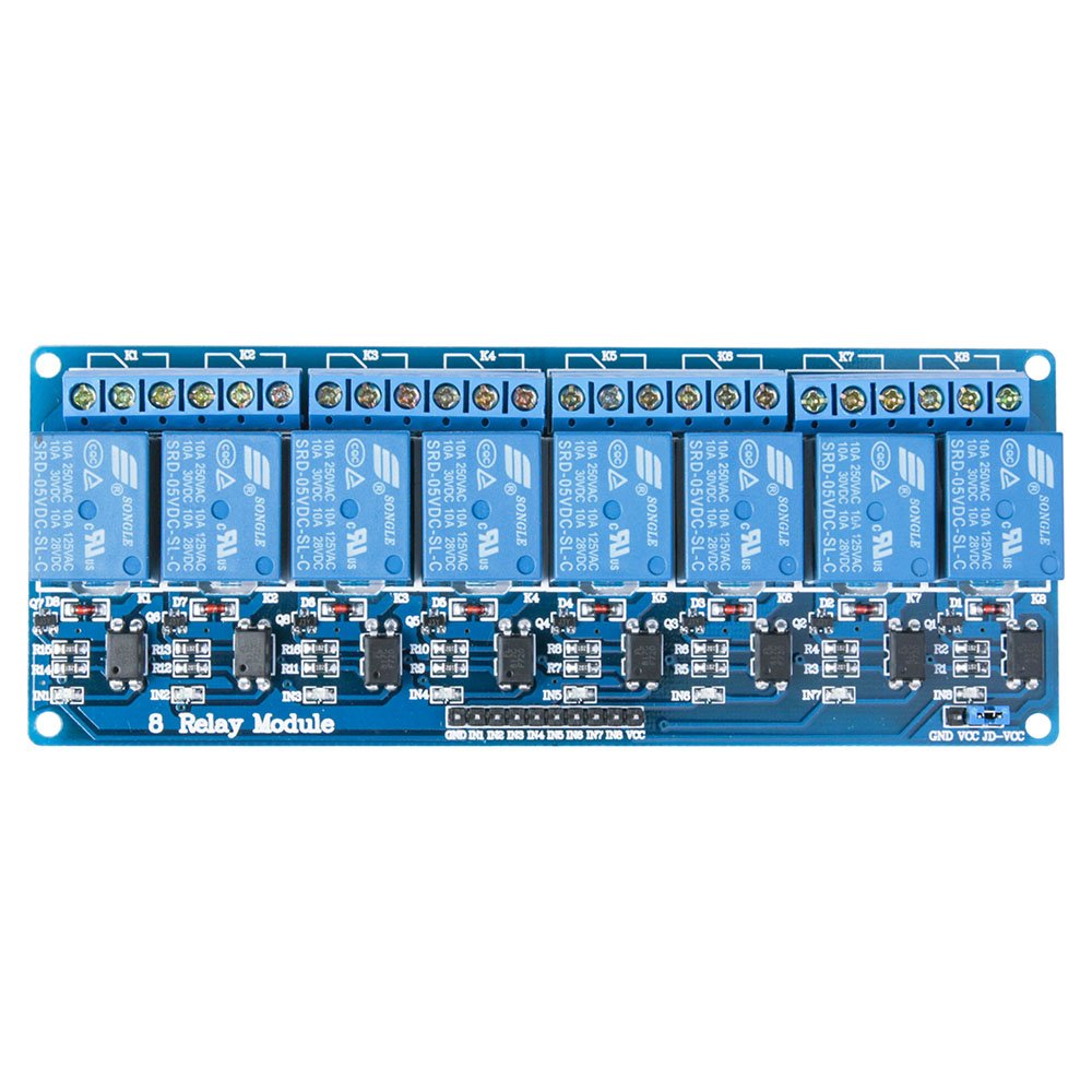
The Relay Tracker is a program written in SASC for the Amiga which sends 16 character binary strings out to the serial port, where it connects to a Raspberry Pi. The Raspberry Pi acts as an interface to two 8 Channel Relay Boards. The Relay Boards can be purchased on Amazon and they only cost around $8. The entire list of materials will be included below.
You may be asking now, well WHAT is the Relay Tracker software used for?
Here is a short video demo which shows how it should be wired up and used.
You may have seen raspberry pi’s or other computers controlling Christmas lights, or other electronic devices and turning them on and off in a sequence. Well the Relay Tracker allows you to use your old school computers such as Amiga, and Commodore 64 to accomplish this task.
To prove that it works we connected a Commodore 64, Commodore 128, and an Amiga 500+ to the relay boards powered by our software, the Relay Tracker for Christmas 2019 and made a video for Youtube. It is more than just a proof of concept video, we synchronized the relays to turn on and off in fancy sequences to the tune of Dance of the Sugar Plum fairies.
Now that you know what the Relay Tracker is, let’s explain how it works, and how to build it.
The software for the Amiga, including the source code, is on our github website. You will need both the Amiga Relay Tracker, and the Raspberry Pi Serial Bridge Python code. It can be downloaded here:
https://github.com/cityxen/RelayTracker
Once you’ve downloaded the software, you must transfer it to your Amiga. The serial bridge python script needs to be placed onto your Raspberry Pi.
In order to assemble the Relay Boards, you’ll need to get some prototyping jumper wires. The jumper wires need to be connected from the Raspberry Pi GPIO pins to the relay boards using the following configuration:
GPIO Pins used for the Relay Boards

GPIO     Relay Board 1
Pin 2    5 volt VCC Relay Board 1
Pin 9    Ground Relay Board 1
Pin 12   Relay 1
Pin 7    Relay 2
Pin 11   Relay 3
Pin 13   Relay 4
Pin 15   Relay 5
Pin 19   Relay 6
Pin 21   Relay 7
Pin 23   Relay 8

GPIO     Relay Board 2
Pin 4    5 volt VCC Relay Board 2
Pin 39   Ground Relay Board 2
Pin 16   Relay 1
Pin 18   Relay 2
Pin 22   Relay 3
Pin 40   Relay 4
Pin 38   Relay 5
Pin 36   Relay 6
Pin 32   Relay 7
Pin 37   Relay 8
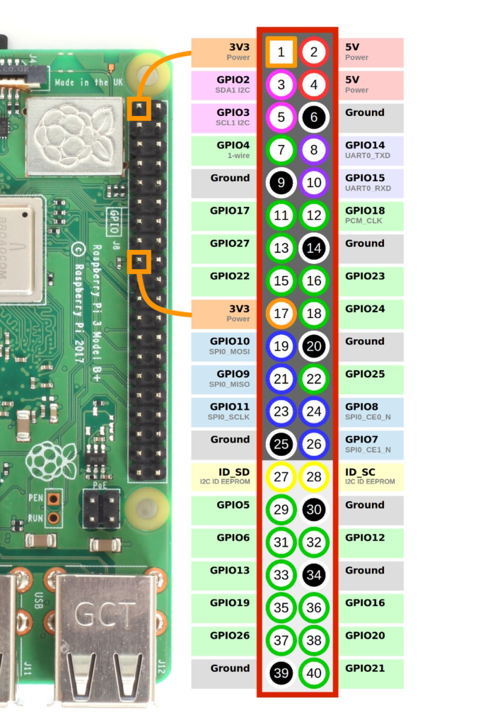
The MAX3232 Serial connector board needs to be wired up to the Raspberry Pi. For the Python script in our repository, this is how it is wired:
GPIO Pins used for the serial device

GPIO     MAX3232
Pin 6    Ground
Pin 8    TXD
Pin 10   RXD
Pin 1    3 volt
Now every thing should be wired up properly and you can run bridge.py python script on the Raspberry Pi. Make sure you have your serial cable hooked up from the Amiga to the Raspberry Pi with a NULL MODEM adapter in between.
The default BAUD speed is 19200, so make sure that your serial.device settings are configured to 19200.
At this point, you should be able to run the Relay Tracker from SHELL by going to the folder where it is and typing rt.
If you don’t provide a track file it will run an internal test pattern.
The list of materials needed for this project:
Fairy Lights https://amzn.to/371GEkY
Copper Cable https://www.digikey.com/product-detail/en/tensility-international-corp/30-01107/T1408-1-ND/9608000
Prototyping Wire https://amzn.to/2LHDNX9
Outlets https://amzn.to/2PSsH34
Outlet Box https://amzn.to/399wGQk
FTCBlock 8 Channel DC 5V Relay Module https://amzn.to/2Xwerh4
Raspberry Pi (Any model with 40 GPIO should work) https://amzn.to/34X5Xnj
The Serial connector board is a MAX3232 based mini board with a 9 pin dsub https://amzn.to/32G9Viv
Null modem required to work with Amiga serial port https://amzn.to/32BrHDC
If anyone has questions, please comment below or send an email to media@cityxen.net
Cheers, Deadline


Leave a Reply